https://mikrotik.com/download/changelogs/
What's new in 6.45.3 (2019-Jul-29 12:11):*) wireless - improved U-APSD (WMM Power Save) support for 802.11e
I also choose to use the HAPac for a number of reasons for this:
- It's relatively inexpensive
- It has two 802.11 radios, one for 2.4GHz and one for 5GHz and both can be used simultaneously
- It's wireless 3 spatial stream capable
- It has a enough wired ports for small configurations, but is extendable with other low-cost products
- It gives me almost everything in a small package - L3 routing/DHCP/DNS/NTP/IGMP querier/vlans/wireless/WPA2-Enterprise radius server/firewall/traffic generator/mirror port/etc; think Swiss army knife for networks.
Many other devices from this vendor will be similar, but not all. When you move into the CRS switches, for example, they have more capable switch chips so some of the configuration would be different. Note that the throughput requirements for this project are relatively low so I do not need line rate Ethernet (L2) switching.
Design 1
Goal:
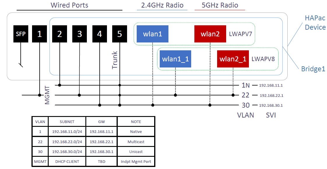
Implement Mikrotik HAPac device to implement this configuration. Two
wireless networks (separate SSIDs) are needed, one for unicast devices, and the other
for multicast based devices. The unicast devices are in 802.11
powersave mode to preserve battery so multicast/broadcast traffic
needs to be controlled (i.e. excluded) as much as possible from this network (vlan 30) .
1.
On Port1, provide for DHCP client so device can be managed out of
band as needed:
/ip
dhcp-client
add
disabled=no interface=ether1
2.
Create bridge1
interface to contain the wireless and wired interfaces:
/interface
bridge
add
igmp-snooping=yes name=bridge1 protocol-mode=none vlan-filtering=yes
3.
Add vlan interfaces (SVI):
/interface
vlan
add
interface=bridge1 name=vlan22 vlan-id=22
add
interface=bridge1 name=vlan30 vlan-id=30
4.
Create wireless subsystem including adding second set of two virtual
interfaces. This includes LWAPV7 SSID using EAP-TLS with the device
acting as RADIUS authenticator and LWAPV8 SSID using WPA2-Personal
with a psk. Root, client, and server X.509 certificates were created
off device and client root/server+key were imported through a manual
operation not documented here.
/interface
wireless security-profiles
set
[ find default=yes ] supplicant-identity=MikroTik
add
authentication-types=wpa2-psk eap-methods=""
group-key-update=1h \
management-protection=allowed
mode=dynamic-keys name=PSK \
supplicant-identity=""
wpa2-pre-shared-key=<super secret goes here>
add
authentication-types=wpa2-eap eap-methods=eap-tls group-key-update=1h
\
management-protection=allowed
mode=dynamic-keys name=EAPTLSLocal \
supplicant-identity=""
tls-certificate=TLS_server.crt_0 tls-mode=\
verify-certificate
/interface
wireless
set
[ find default-name=wlan1 ] band=2ghz-g/n country="united
states" \
disabled=no
frequency=2437 mode=ap-bridge security-profile=EAPTLSLocal ssid=\
LWAPV7
vlan-id=30 vlan-mode=use-tag wireless-protocol=802.11 wmm-support=\
enabled
add
disabled=no keepalive-frames=disabled mac-address=E6:8D:FF:FF:FF:FF \
master-interface=wlan1
multicast-buffering=disabled name=wlan1_1 \
security-profile=PSK
ssid=LWAPV8 vlan-id=22 vlan-mode=use-tag \
wds-cost-range=0
wds-default-cost=0 wps-mode=disabled
set
[ find default-name=wlan2 ] band=5ghz-a/n/ac country="united
states2" \
disabled=no
frequency=5825 mode=ap-bridge security-profile=EAPTLSLocal \
ssid=LWAPV7
vlan-id=30 vlan-mode=use-tag
add
disabled=no keepalive-frames=disabled mac-address=E6:8D:FF:FF:FF:FF \
master-interface=wlan2
multicast-buffering=disabled name=wlan2_1 \
security-profile=PSK
ssid=LWAPV8 vlan-id=22 vlan-mode=use-tag \
wds-cost-range=0
wds-default-cost=0 wps-mode=disabled
5.
Add interfaces to the bridge:
/interface
bridge port
add
bridge=bridge1 interface=wlan1
add
bridge=bridge1 interface=wlan2
add
bridge=bridge1 interface=wlan1_1
add
bridge=bridge1 interface=wlan2_1
add
bridge=bridge1 hw=no interface=ether2
add
bridge=bridge1 hw=no interface=ether3 pvid=22
add
bridge=bridge1 hw=no interface=ether4 pvid=30
add
bridge=bridge1 hw=no interface=ether5
6.
Configure VLANs on the bridge:
/interface
bridge vlan
add
bridge=bridge1 tagged=bridge1,ether5,wlan1_1,wlan2_1 untagged=ether3
\
vlan-ids=22
add
bridge=bridge1 tagged=bridge1,ether5,wlan1,wlan2 untagged=ether4 \
vlan-ids=30
7.
Add IP addresses to the various interfaces:
/ip
address
add
address=192.168.11.1/24 interface=bridge1 network=192.168.11.0
add
address=192.168.22.1/24 interface=vlan22 network=192.168.22.0
add
address=192.168.30.1/24 interface=vlan30 network=192.168.30.0
8.
For convenience, add DHCP capability for each supported VLAN:
/ip
pool
add
name=pool1 ranges=192.168.11.200-192.168.11.240
add
name=pool22 ranges=192.168.20.200-192.168.22.240
add
name=pool30 ranges=192.168.30.200-192.168.30.240
/ip
dhcp-server
add
address-pool=pool1 disabled=no interface=bridge1 lease-time=1d name=\
server1
add
address-pool=pool22 disabled=no interface=vlan22 lease-time=1d name=\
server22
add
address-pool=pool30 disabled=no interface=vlan30 lease-time=1d name=\
server30
/ip
dhcp-server config
set
store-leases-disk=immediately
/ip
dhcp-server network
add
address=192.168.11.0/24 gateway=192.168.11.1
add
address=192.168.22.0/24 gateway=192.168.22.1
add
address=192.168.30.0/24 gateway=192.168.30.1
9.
Set WMM priority for 802.11 frames as they are transmitted from this
device over WiFi (optional)
/interface
bridge filter
add
action=set-priority chain=forward in-bridge=bridge1 mac-protocol=vlan
\
new-priority=6
passthrough=yes vlan-id=30
10.
Manage IGMP snooping: enable PIM to activate an IGMPv2 querier:
/routing
pim interface
add
interface=vlan22
For
WPA2-Enterprise configuration, XCA tool (http://hohnstaedt.de/xca)
was used to create the following, all using RSA keys due to specific
product limitations in use:
-
Server key pair and self-signed server certificate. Once both imported as PEM format, separately, cert first, it is named TLS_server.crt_0. Since this is self-signed, it must be placed on each device, i.e. using certificate pinning.
-
Root key pair and self-signed rootCA for client signing. Since server is self-signed, this is not needed for validating the server certificate but is used to verify client certs. Import just the root X.509 certificate to the box so the clients can be authenticated.
-
On factory reset of device, even though I have the config file, I found I need to import the X.509 certificates first before wireless configuration will import.
If
enterprise authentication on WiFi is not needed, just use a psk with
WPA2-Personal. Choose this profile when setting up the wlan
configurations (for this example, this is the PSK
profile).
As
is often the case, the same SSID is available on either 2.4 or 5GHz
bands (i.e. b/g/n or a/n/ac). Also two separate networks are needed
for different device types here so they are bridged to separate
vlans. If this box is uplinked, a trunk port is provided (so other
side must be configured to trunk as well) or for very small
implementations that just need separate networks and some unicast
routing across vlans, use the access ports provided on ports 3 &
4.
Configuration 2: Only access ports for VLAN22

Presume that we only need Access ports on VLAN22, so ether2/3/4 are all on this VLAN now. Changes would be:
5.
Add interfaces to the bridge:
/interface
bridge port
add
bridge=bridge1 interface=wlan1
add
bridge=bridge1 interface=wlan2
add
bridge=bridge1 interface=wlan1_1
add
bridge=bridge1 interface=wlan2_1
add
bridge=bridge1 hw=no interface=ether2 pvid=22
add
bridge=bridge1 hw=no interface=ether3 pvid=22
add
bridge=bridge1 hw=no interface=ether4 pvid=22
add
bridge=bridge1 hw=no interface=ether5
6.
Configure VLANs on the bridge:
/interface
bridge vlan
add
bridge=bridge1 tagged=bridge1,ether5,wlan1_1,wlan2_1
untagged=ether2,\
ether3,ether4
vlan-ids=22
add
bridge=bridge1 tagged=bridge1,ether5,wlan1,wlan2 vlan-ids=30
Performance
I know this design will cause switched frames to be handled by CPU, so for high data traffic, this may not be the best design (there are other solutions like using the switch chip directly). What can this do?
With
bridge set to vlan filtering, CPU does all forwarding at layer 2 &
3; this can make it difficult to get full line rate from switching.
A look at performance of the system with two wired iperf clients on
vlan22. We can see that we are getting about 1GBps (basically full
line rate) for one connection at a cost of most of the CPU.

To
support more devices on VLAN22, we can add a managed L2 switch with
IGMP snooping, with or without VLANs.
No comments:
Post a Comment